Thermal Cycle Testing of PWBs – The Robust PWB
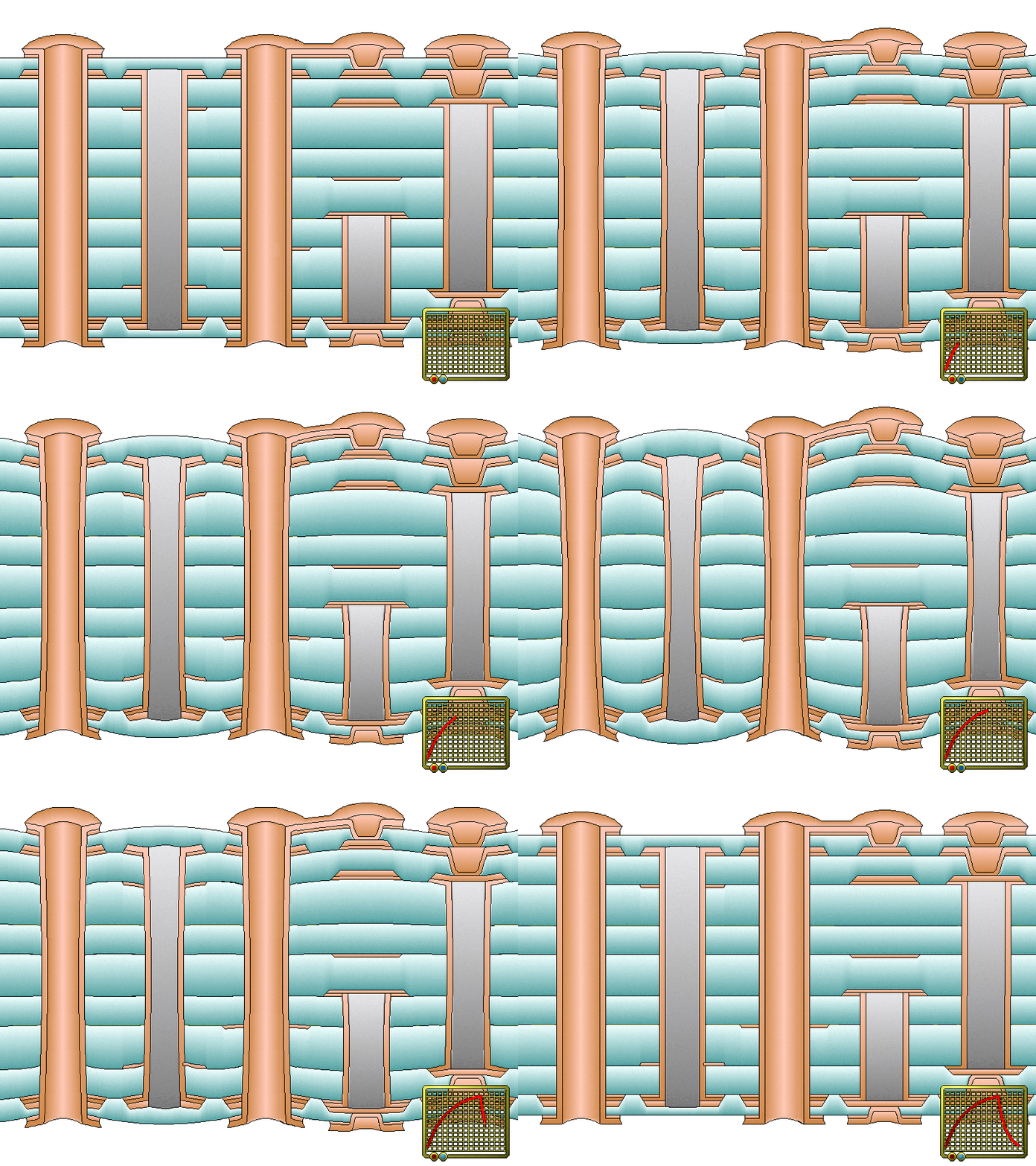
This animation represents a typical thermal cycle of a robust coupon that does not fail.
The animation serves to establish the relative effect of a thermal excursion on a PWB heated
to assembly temperatures. This animation demonstrates how the dielectic material expands
from the middle of the board. The degree of material displacement increases from the middle
of the board out ward with the maximum displacement occurring at the surface layers.
The PTH structures act like small rivets constraining the z-axis expansion of the dielectric
material. The dielectric bulges out between the constraining PTHs. The coefficient of
thermal expansion (CTE) of the dielectric material is usually an order of magnitude larger than
the CTE of copper. This mismatch between the CTE of the dielectric material and the copper create
significant stress in the PWB and is the primary cause of interconnection failures.
Note in this animation of a robust coupon that the copper is malleable
and complies with the expanding dielectric material. The PTH exhibits a slight inward bow
in the central zone during the thermal expansion as the compressive forces on the x-axis and
y-axis deform the copper barrel inward. The pad rotation on PTH and buried vias is up and away
from the middle of the PWB. The microvia however, floating between the PTHs, has a pad
rotation down, toward the middle of the PWB. The buried vias exhibit a deformation that is
localized and of a lesser magnitude than the adjacent PTH based on its lower position in
the structure. The PTHs, buried vias and microvias all influence the deformation of the material
that is in close proximity and on adjacent structures.
