
PWB Reliability
Each of the failure modes listed below addresses PWB reliability from a pathologist’s point of view.
The focus is on thermally induced PWB failure modes and is based on lessons learned over years of thermal
cycle testing and failure analysis. Each entry below explores a failure mode, how damage propagates during
thermal cycling, and includes an animation of the failure as it develops during thermal excursions.
To learn more about each failure mode, click on the images below. The explanations are also accompanied by animations which demonstrate the failure.
Although the test method upon which these entries are based is Interconnect Stress Testing (IST),
the information offered is applicable to all thermal cycle test methods. IST is a thermal cycle test
method that heats representative coupons to a test temperature while monitoring changes in resistance on
two or more discreet circuits. The method allows each coupon to be heated in dependently.
Testing coupons independently facilitates having testing stop when either the heating or sense circuits
exceeds a 10% increase in resistance (failure). Testing stops within two seconds of failure. By stopping
the test within seconds of violating the 10% threshold in resistance we can evaluate failure modes in the
circuits before catastrophic damage occurs which can mask failure modes and producing artefact conditions
that may confound analysis. We are able to stop as the failure is “ripening” as it were. Because the failure
is a 10% increase in resistance we are able to apply a small current to the failing circuit while observing
the coupon with a thermal camera. A hot spot will direct us to the single most “insulted” interconnect be
it a plated through hole (PTH), blind via, buried via or microvia, in the coupon.
A microsection is processed and by comparing the failing structure to adjacent less damaged structures,
significant insight to the cause of failure may be gained. The failure modes described in these entries are
applicable to any thermal cycle testing method, failures and rework and field failures related to wear out
induced by thermal cycling (as opposed to mechanical damage like vibration etc.).
A microsection of a PWB is of a structure at ambient. At ambient the material is contracted, strain and stress is at its lowest. In order to gain insight as to how failures are developing I began animating failures based on observations of static microsections and, data from thermal mechanical analysis (TMA). With clues from those methods I was able to anticipate how circuit boards expand during thermal excursions.
Graphs of resistance increases in circuits plotted against thermal cycles gives insight as to how failures evolve over time. Animating the failure mode forced me to look at the failure from a new point of view. The objective findings of “cycles to failure” combined with the “subjective interpretation” of microsections, frequently resulted in conclusions that confirmed intuition but, occasionally, the new insight was counter intuitive, flying against conventional wisdom.
The PWB forms a mechanical platform, an electrical interconnection between components, a conductor for heat dispersion, and provides protection for sensitive components. The modern circuit board is frequently a multilayered, complex component that is an integral part of electronic devices. Generally robust, PWBs may fail either in assembly and rework or in the end use environment particularly when after “lead free” solder assembly and rework. PWB failures may occur in the copper interconnections or the dielectric material. Although there are a number of established quality requirements to assure compliance, PWBs can, and do, fail in assembly and in the end use environment.
One could place the major influences to PWB reliability under one of four groups:
• copper quality
• material robustness
• design influence
• other less frequently influential variables like lamination, drilling, hole preparation etc.
Copper quality, material robustness and design influences are commonly the dominant influences affecting PWB reliability. In practice we find that these influences can work in concert or in competition with each other to establish the over all reliability of PWBs.
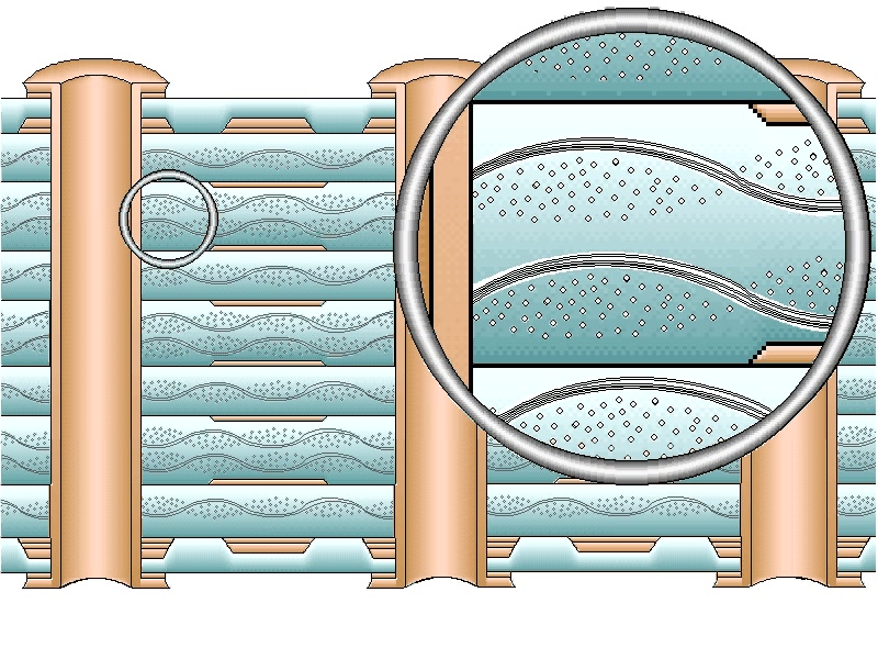
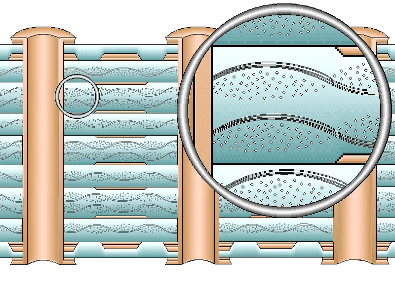
The animations offered in these entries will, for the most part, be of a cross sectional view through interconnects structures. Most of the animations will be oriented on a plane bisecting PTH, blind and buried vias, and microvia interconnections. This representative configuration has been animated to show how types of failures may develop.
These animations are not to be considered accurate in scale but rather an artistic rendering, with key features enhanced to improve understanding of various failure modes. For expediency the animations demonstrate, in one or two thermal cycles, the accumulated damage that may occur over hundreds of thermal excursions. It is best to play the animations in a continuous loop.
Failure Modes
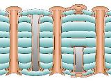
Thermal Cycle Testing of PWBs – The Robust PWB
This animation represents a typical thermal cycle of a robust coupon that does not fail. The animation serves to establish the relative effect of a thermal excursion on a PWB heated to assembly temperatures. This animation demonstrates how the dielectic moves.
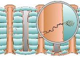
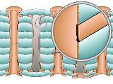
PWB Barrel Cracks – Wear Out Failures
When exposed to thermal cycle testing, cracks that develop slowly in the copper barrel of plated through holes (PTH) is considered to be a wear out failure mode. This failure mode is often observed in boards that survive hundreds or thousands of thermal cycles and is the failure mode of robust PWBs.
PWB Barrel Cracks – Accelerating Failure
Cracks in the barrel of the PTH advance through the metallization and the electrodeposited copper layers, propagating through copper crystals, and traversing the barrel in a straight and horizontal path. The cracks are frequently found to be open upon microscopic review.
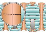
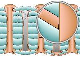
Corner Crack
Moving up the barrel we come to the knee of the PTH, the corner. Corner cracks are much like barrel cracks that moved up to the knee of the PTH. Notice in the animation that the greatest deflection of the material is at the outer surfaces. Pad rotation is the degree of deflection of a pad out of plane with the copper.
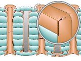
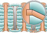
Interconnect Separation
Armed with thermal cycles to failure data, damage accumulation profiles and interpreted with microsection evaluation of failure sights, we are able to classify most failures, for the purposes of these columns, as interconnect separations, post separations and foil cracks. Each failure mode exhibits distinct a presentation and a different liability in assembly and the end use environment.
Post Separation
Thermal cycle testing where the resistance of the tests circuits are measured every few seconds and testing stops immediately when an individual coupon fails (10% increase in resistance) allows the ability to apply a small current to the failed coupon, while observing the coupon under a thermal camera in order to identify the one failing interconnections out of hundreds.
Surface Finish and PWB Reliability
There are two ways in which metallic surface finishes, on exposed traces and pads, can affect PWB reliability results when tested with thermal cycling. The surface finish can have a direct influence by extending or reducing cycles.
Foil Cracks
A third type of interconnect failure may best be described has a foil crack. This failure mode
appears with cracks in the internal foil on layer
two and layer N-1 (the first internal layer up from the bottom of the board) on high layer count boards.
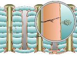
Conductive Anodic Filament (CAF) Failure
Conductive Anodic Filament (CAF) formation is a well-studied phenomenon that is driven by chemical, humidity, voltage, and mechanical means. It is characterized by a sudden loss of insulation resistance that happens internally in the PCB.
Crazing
This condition may be described as a separation between the epoxy and individual glass fibers. This is a more insidious failure mode, in that there are no obvious visible cracks, but it can be seen as light refraction observed along glass fibers that are parallel with the plane of the microsection.